Did not you find what you were looking for? Ask us! We have archives of 140 TB. We have all modern reuse projects and renovation projects for Soviet standard buildings. Write to us: info@proekt.sx
Zoo. feed kitchen

Plot area, m2: 2235,0
Building area, m2: 480,0
Total area, m2: 1030,0
Construction volume, m3: 3900,0
Estimated cost at the 2001 base price level (without VAT)
Total: thousand rubles: 8
Construction and installation works thousand rubles: 4
Equipment, thousand rubles: 2682,07
Other expenses, thousand rubles: 660,53
including:
PIR thousand rubles 280,00
refundable amounts thousand rubles 17,41
Estimated cost at May 2010 base price level (VAT included)
Total: thousand rubles: 42
Construction and installation works thousand rubles 30
Equipment thousand rubles 8
Other expenses, thousand rubles: 3
including:
PIR thousand rubles: 855,68
VAT thousand rubles: 6
refundable amounts, thousand rubles: 110,40
Architectural and space-planning solutions
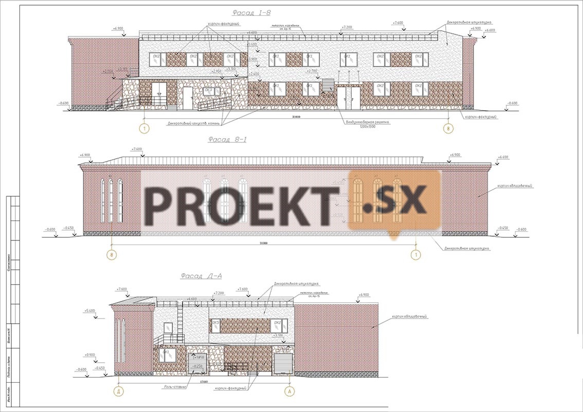
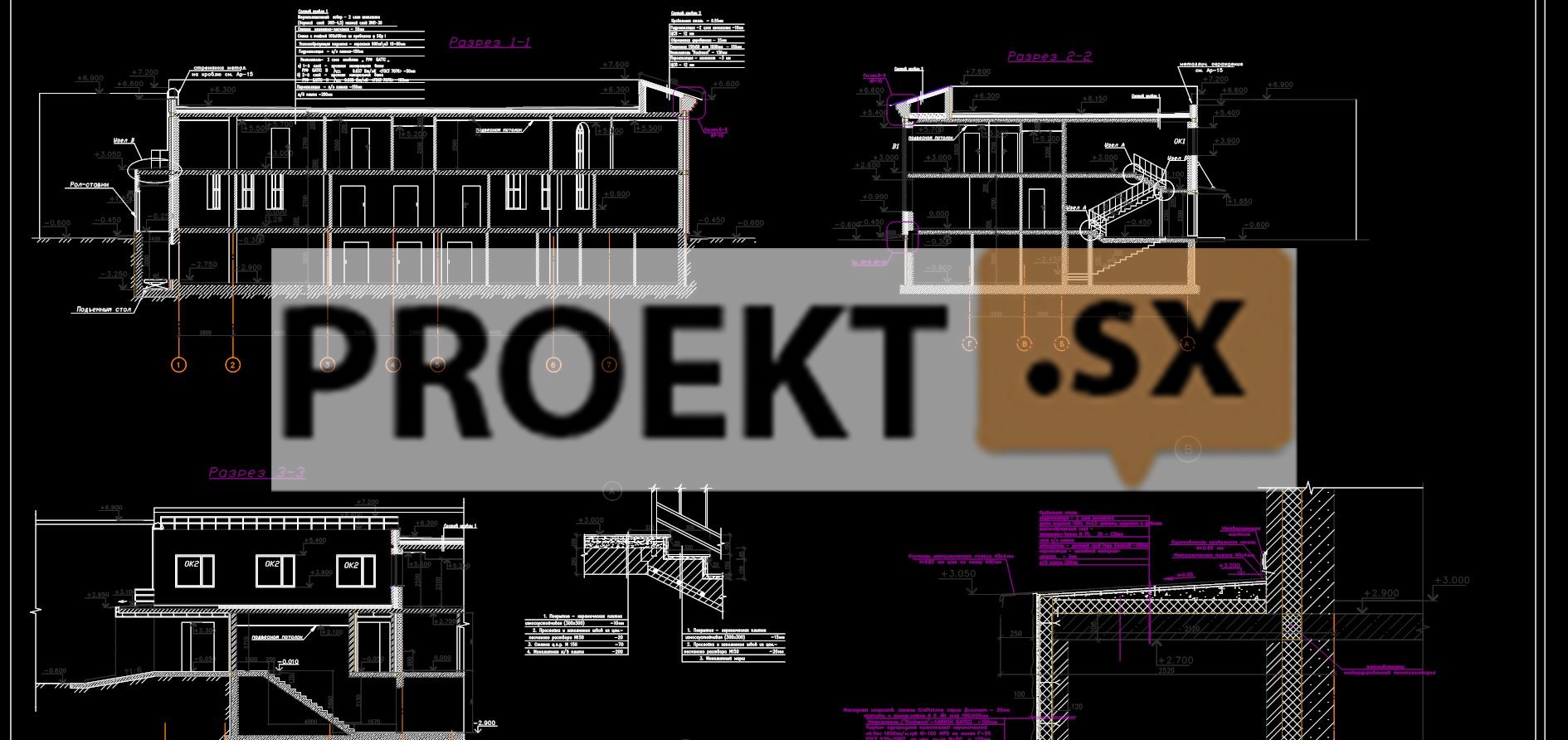
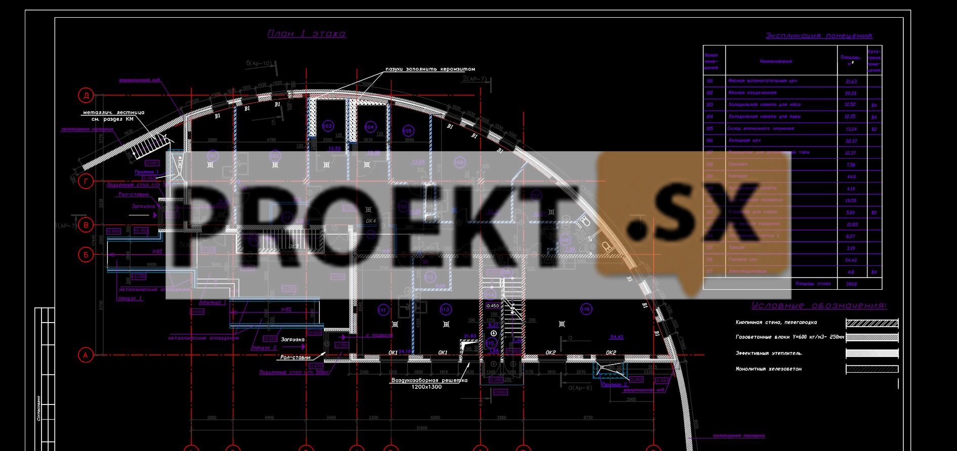
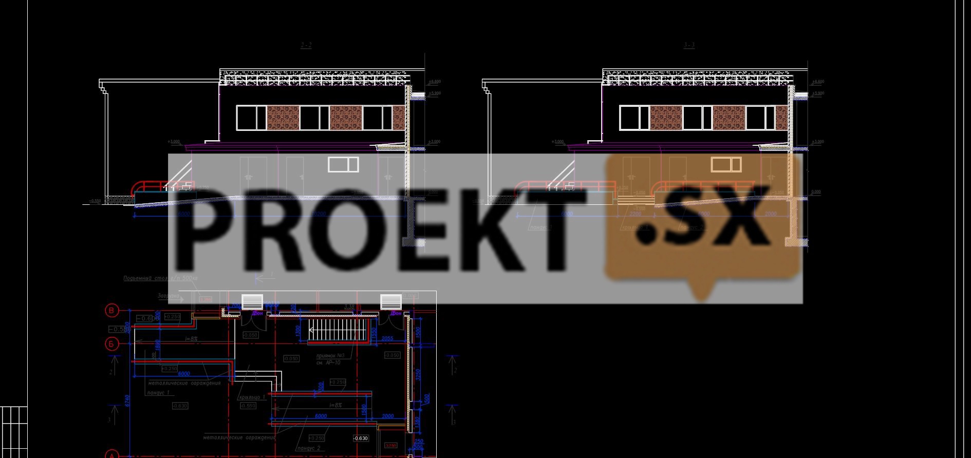
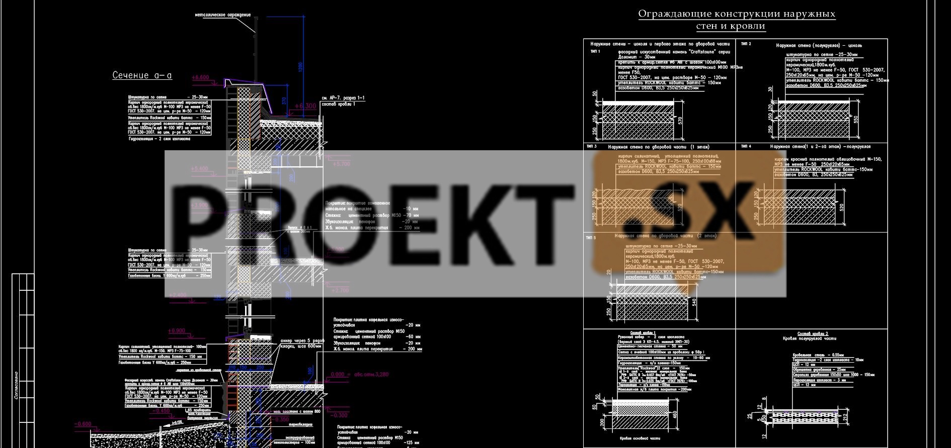
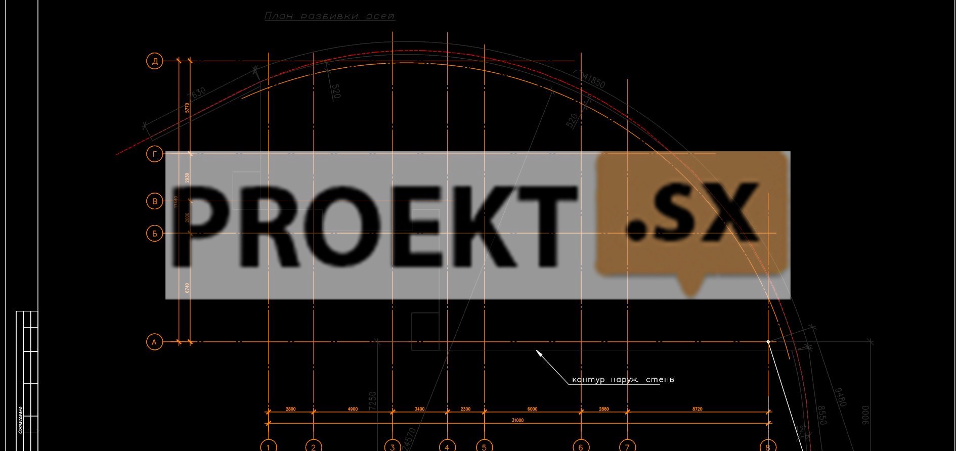
The designed pavilion "Kitchen" is a two-story building with a basement, of complex shape in plan with a maximum size of 31,0 x 17,4 m and a height of 7,6 m to the top of the roof. The feed kitchen is designed for receiving, accumulating, preparing and processing feed raw materials, receiving and accumulating individual components in finished form, preparing wet mixtures and dispensing them into mobile animal delivery vehicles. On the floors of the building, the design documentation provides for the placement of: in the basement - storage rooms, refrigerators, containers, pantry inventory and facilities for engineering support of the building; on the ground floor - a temporary storage warehouse, a meat cutting room, cold stores, large and small weighing shops, a cold shop, a meat auxiliary shop, a pantry for bread and a hot shop; on the second floor - the offices of the supply manager, the head of the department, the chief livestock specialist, the heads of material and food warehouses, dressing rooms with showers for those working in the feed kitchen and eating rooms. Bathrooms are designed on the first and second floors of the building. The building provides for the installation of two lifting tables with a load capacity of 500 kg each for the delivery of products from the basement to the first floor. The roofs of the building - roofing steel on a wooden crate with an external drain and rolled steel with an internal drain. Facade artificial stone "Craftstone", mesh plaster, front and silicate bricks were used in the exterior decoration of the building.
Structural and space-planning solutions
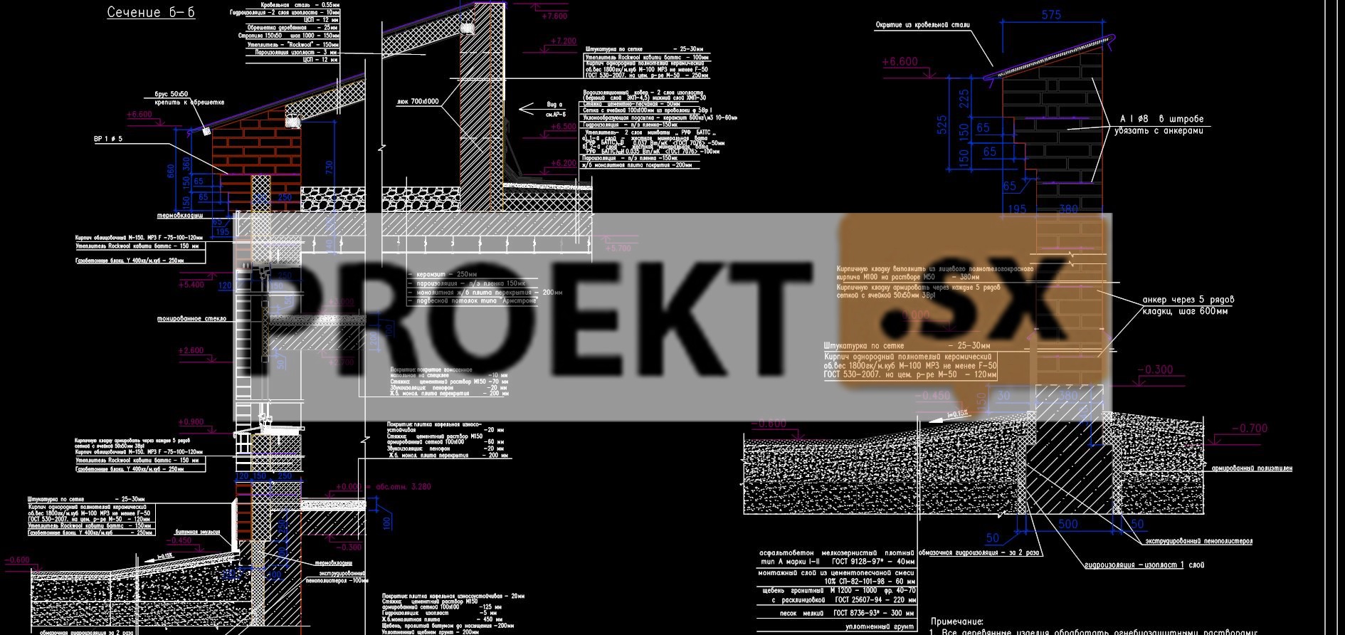
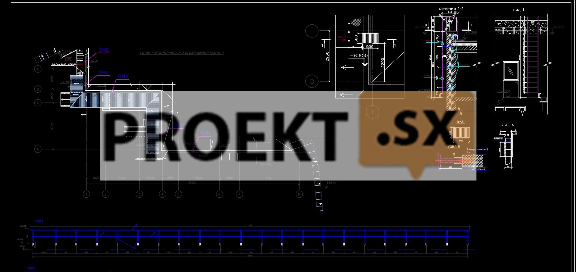
The level of responsibility of the building is II, normal. The building was designed according to the column-wall structural scheme. The material of the supporting structures is monolithic reinforced concrete, concrete class B25, F75, reinforcement of classes AIII, AI. Columns with a section of 400 x 400 mm, along the outer contour of the building with a section of 250 x 500 mm. The frame columns are designed in increments of 2,93 to 6,0 m. The basement walls are external - 300 mm thick, internal - 200 mm thick. The internal load-bearing walls of the building are 200 mm thick. External walls are non-bearing, multi-layer, with floor-by-floor support on floors. The inner layer is made of aerated concrete blocks of grade B3,5, F35 250 mm thick, the middle layer is made of rigid mineral wool insulation 150 mm thick. The outer layer is 120 mm thick, depending on the architectural design of the facades: from silicate brick M 125, F75 or full-bodied ceramic brick M 100, F50, partially finished with plaster and facade decorative stone. The connection of the layers and the fastening of the walls to the supporting frame is carried out by flexible connections with an anti-corrosion coating. Floor slabs and coatings - monolithic reinforced concrete beamless 200 mm thick. Along the perimeter of the building, in the protruding parts of the ceilings, inserts made of effective insulation are provided to prevent freezing. Stair flights - monolithic reinforced concrete. The elevator shaft is made of solid brick M100 on a cement-sand mortar M50 with a thickness of 250 mm. The spatial rigidity and stability of the building is ensured by the joint work of the vertical load-bearing elements of the building with interfloor ceilings. The calculation of load-bearing structures and foundations was carried out using the Stark ES 2010 program. The foundation is on a natural base from a monolithic reinforced concrete slab 450 mm thick made of concrete class B25, W6, F50. Under the foundations, concrete preparation is provided from concrete of class B7,5 with a thickness of 100 mm. The relative elevation of 0.000 is taken as the absolute elevation of 3,280 m. In accordance with the report on engineering and geological surveys, the basis of the foundation is the EGE-2 soils (medium-sized gray sands of medium density saturated with water with E = 250 kg / cm2, e = 0,7, φ = 33º) and EGE 3 (fine sands gray medium density saturated with water with E=230 kg/cm2, e=0,7, φ=30º). The calculated resistance of the base soil is 1,79 kg/cm2, the average pressure on the base soil is 0,43 kg/cm2. Expected draft 3,0 cm. The maximum level of groundwater is expected during the period of heavy precipitation and snowmelt at a depth of 0,8 m from the earth's surface. Groundwater is non-aggressive towards concrete of normal permeability. The project provides for measures to protect the basement from groundwater: drainage, coating waterproofing of the basement walls. The normative depth of soil freezing is 1,45 m. Along the perimeter of the building from the outside, it is planned to insulate the monolithic walls of the basement with an effective insulation 100 mm thick. The fencing of the territory was designed from solid brick M100 F50 on mortar M50, 380 mm thick, 6,6 m high. The foundation for the fence is made of cast-in-situ reinforced concrete of class B25, W6, F75 on a natural base, taking into account the depth of freezing.
Engineering equipment, utility networks, engineering activities
Water supply (cold water) for consumers of the facility, in accordance with the specifications, is provided from the public water supply network D = 225 mm, passing through the territory of the zoo through one input from polyethylene pipes PE100 D = 90x 5,4 mm. At the inlet, a water meter assembly is installed according to TsIRV 02A.00.00.00 sheets 26, 27, with a bypass line with a diameter of DN = 80 mm. On the fire line, a valve with an electric drive is installed. Guaranteed pressure at the connection point - 28 m. water Art. Estimated consumption of cold water 9,2 m3/day, including: for household and drinking needs - 0,80 m3/day; for irrigation of the adjacent territory - 2,25 m3/day; for production needs - 6,11 m3/day. The building has an integrated plumbing system. The required pressure for the drinking water supply system is 19,7 m. The system of the combined domestic drinking and fire-fighting water supply is a dead-end. Galvanized steel pipes for water and gas pipelines according to GOST 3262-75 were selected for the installation of the system. For watering the territory, along the perimeter of the building, two watering taps D = 25 mm are installed. Water consumption for internal fire extinguishing - 2,6 l / s. Number of fire hydrants D=50mm - 6 pcs. The required pressure for the internal fire extinguishing system is 21,9 m. External fire extinguishing is provided from a fire hydrant D = 125 mm installed on the public water supply network of a water supply system D = 225 mm passing through the territory of the zoo. Water consumption for external fire extinguishing - 10 l / s. To prepare hot water for the DHW system in the IHS of the Feed Kitchen pavilion, a heat exchanger is installed, and for the period of heat outage, an electric boiler is installed in the IHS. The DHW system is with a circulation pipeline. For laying main pipelines and risers of the DHW system, steel galvanized water and gas pipes were selected according to GOST 3262-75. The estimated consumption of hot water for household and drinking needs is 0,13 m3 / day. For the production needs of the feed kitchen - 2,15 m3 / day. Hot water temperature (Тз) – 65°С. The required pressure to the boiler is 24 m of water column. Disposal of household wastewater in the amount of 9,19 m3/day, rainwater runoff with a flow rate of 6 l/sec and drainage runoff with a flow rate of 0,11 l/sec is provided for in well No. 116 on a combined sewer network passing through the territory of the zoo. For laying the domestic sewer network, PVC pipes D = 160 mm were selected. The following systems are designed for the building: domestic sewerage; industrial sewerage system for the removal of wastewater from the production workshops of the feed kitchen. internal drains. Submersible drainage pumps-GNOM 10-8 were designed to remove wastewater from basements (ITP and water metering unit). For the construction of domestic and industrial sewerage systems, PVC pipes for internal systems were selected. Pressure polyethylene pipes according to GOST 6942-98 were selected for the installation of an internal drainage system. Heat supply is provided in accordance with the conditions. The source of heat is the boiler room through the central heating and TC-4. Thermal load at DHWmax - 0,0129 Gcal/hour, at DHWavg - 0,00669 Gcal/hour. The heat carrier is water with Т1/Т2 = 95/70°С. Design pressure at the connection point: P1-P2 = 7 m.w.st., P2 = 30 m.w.st. The heat supply scheme is two-pipe. Laying of a heat network - channelless and in channels (at corners of rotation). For laying a heating network, it is planned to use a pipeline made of seamless steel pipes in accordance with GOST 8732-78 * VST3sp GOST 8731-74 (group B) with thermal insulation made of polyurethane foam PPU-345 without ODK. Compensation for thermal elongations is solved by means of bellows expansion joints. The scheme of connection of heating systems - dependent, hot water systems - through a heat exchanger. To receive thermal energy, adjust the parameters of the coolant and supply heat to consumers, an individual heating point (ITP) with automatic devices, a set of shut-off and control and safety valves, heat metering units, water heaters and mixing and circulation pumps is provided. Telephonization of the building is provided in accordance with the contract. Radiofication - in accordance with TU. The design documentation provides for the laying of a distribution feeder line to the Feed Kitchen building, taking into account the requirements for civil defense and emergency situations. To control the functioning of the engineering equipment of the building, a dispatching system is provided with the output of signals to the central control room. In order to receive television programs, in accordance with the ToR of the Construction Committee and the appendix to the design assignment, it is planned to install antennas and a headend station on the building being designed. Power source - PS 165 (2s.sh., 1s.sh.). Power supply, in accordance with the specifications, is provided from RU-0,38 kV (shield No. 1 and No. 2) TP-1633 through two designed cable lines. The number of cables in the cable line is one. Cable PvBbShv -2 (4x50) is accepted for laying. The design load for the second category in terms of power supply reliability is 76,76 kVA. Consumers of the 1st category in terms of power supply reliability include security and fire alarms, a heating point, emergency and evacuation lighting. To provide consumers with the first category of reliability, an ATS device is provided in the main switchboard. The backup power supply of these consumers is from a storage battery, KL250P with a power of 15,0 kVA. Estimated load according to the 1st category of reliability is 14,85 kVA. Mains voltage-380/220v. TN-CS earthing system. For the distribution of electricity to consumers, a main switchboard with an additional (third) section fed through the ATS is provided. To account for the consumed electricity, a 3-phase meter (TsE 2727 10-100A) is installed in the main switchboard, with switching on through measuring transformers. Power shields are provided for distribution of electricity between pantographs. For the distribution network device, the VVGng cable was selected. To illuminate the premises, LED lamps with a power of 32W, 30W and 3W were selected, which meets the requirements of the optimization concept schemes. To ensure electrical safety, a potential equalization system and installation of protective devices are provided. Lightning protection - on the third level of protection. To illuminate the territory, LED lamps are provided, installed above the ramps in the loading and unloading area, under the canopies, the installation height is 2,8 m. The heat carrier in heating and heat supply systems is water with a temperature of - 95-70°C. A two-pipe dead-end heating system was designed for the building with the distribution of main pipelines above the basement floor. Heating devices - steel panel radiators, in the switchboard room - registers made of smooth pipes. To remove air from the heating system, it is planned to install air outlet valves on heating appliances and automatic air collectors on risers at the upper points of the system. On the risers, the installation of shut-off and balancing valves is provided. Draining the heat carrier of the heating system - in the ITP room. For the installation of the heating system, steel water and gas pipes (mains) and polypropylene pipes (risers and inlets) were selected. The building is provided with supply and exhaust ventilation with mechanical stimulation. Exhaust ventilation with natural impulse is provided in the switchboard room. Ventilation systems are designed separately for each floor and depending on the functional purpose of the serviced premises. There is a separate exhaust ventilation system for the bathrooms on the first and second floors. Placement of ventilation equipment - in ventilation chambers in the basement and on the second floor of the building. Air exchanges in the premises are determined in accordance with the requirements of SNiP and SaNPiN: according to the calculation for compensation of local exhausts, according to the standard exhaust air flow for the bathrooms and shower rooms, according to the standard multiplicity for the rest of the premises. An air-thermal curtain of the loading zone is provided above the entrance doors. Measures for noise suppression and fire protection are provided. Systems of local suctions from the technological equipment of the hot shop were designed.