Did not you find what you were looking for? Ask us! We have archives of 140 TB. We have all modern reuse projects and renovation projects for Soviet standard buildings. Write to us: info@proekt.sx
Project of a stationary snow melting point

The construction of a stationary snow melting point is being planned. According to the terms of reference (Appendix 2), the construction is being designed:
- snow-melting chamber - dimensions in terms of 42,0 x 22,0 m, on a monolithic reinforced concrete slab with a laying depth of 6,0 m;
- a complete pumping station - with a diameter of 2,5 m, with a laying depth of 9,0 m;
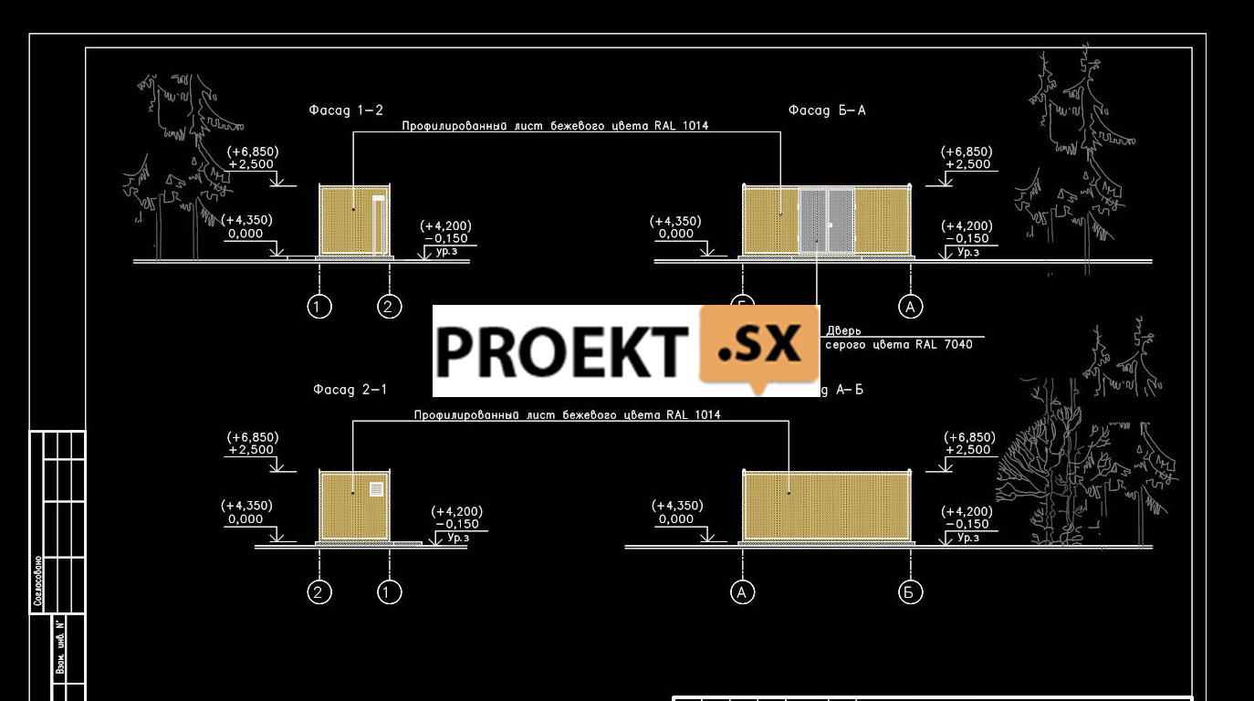
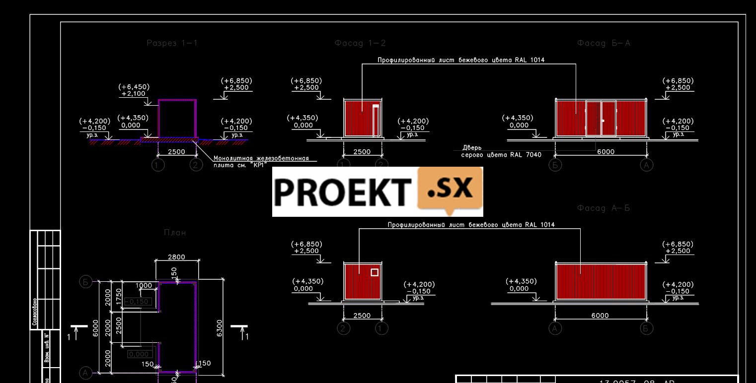
- control pavilion - 6,0 m high, 3,0 x 6,0 m in plan, with a laying depth of 2,0 m;
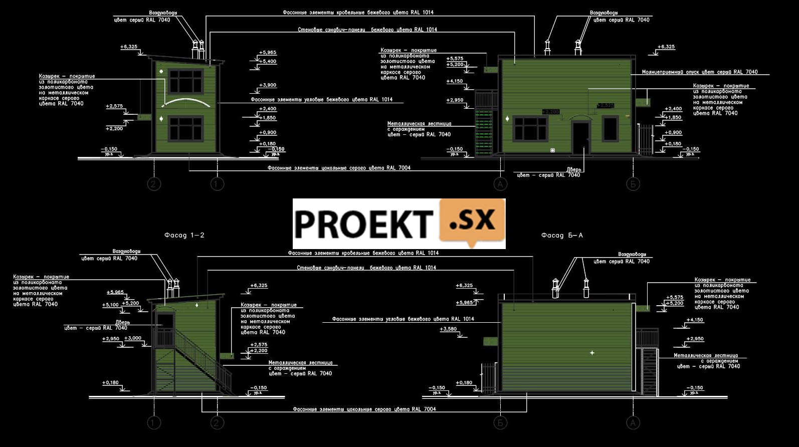
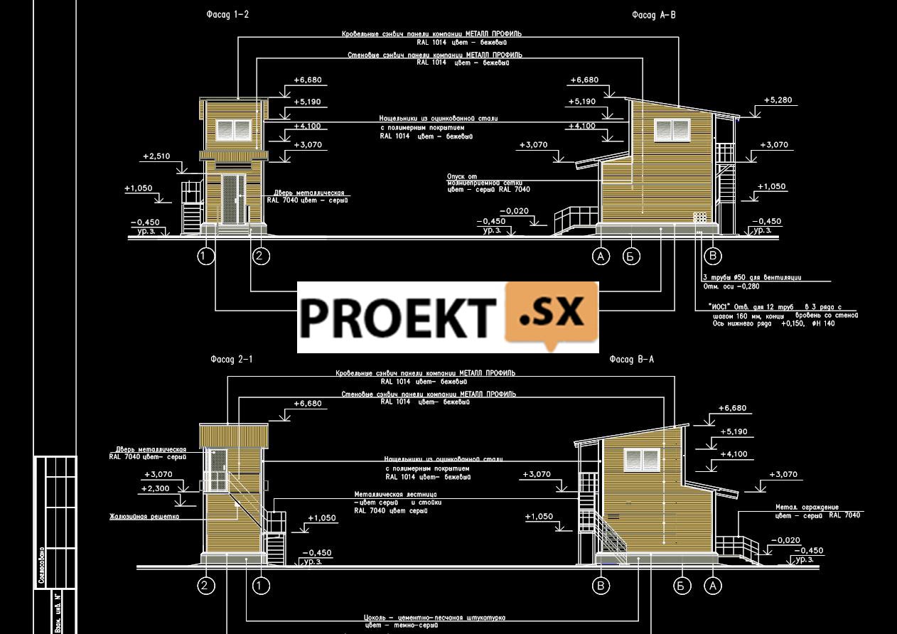
- checkpoint - 6,0 m high, 12,0 x 3,0 m in plan, with a laying depth of 0,0 m;
- BKTP - 4,0 m high, 3,0 x 6,0 m in plan, with a laying depth of 2,0 m;
- connection chamber - dimensions in terms of 5,0 x 5,0 m, with a laying depth of 8,0 m;
- sewerage networks at depths up to 6,0 m, laying method - HDD;
- water supply networks at depths up to 5,0 m in an open way in a trench and closed HDD crossings;
- access road with a depth of 0,5 m.
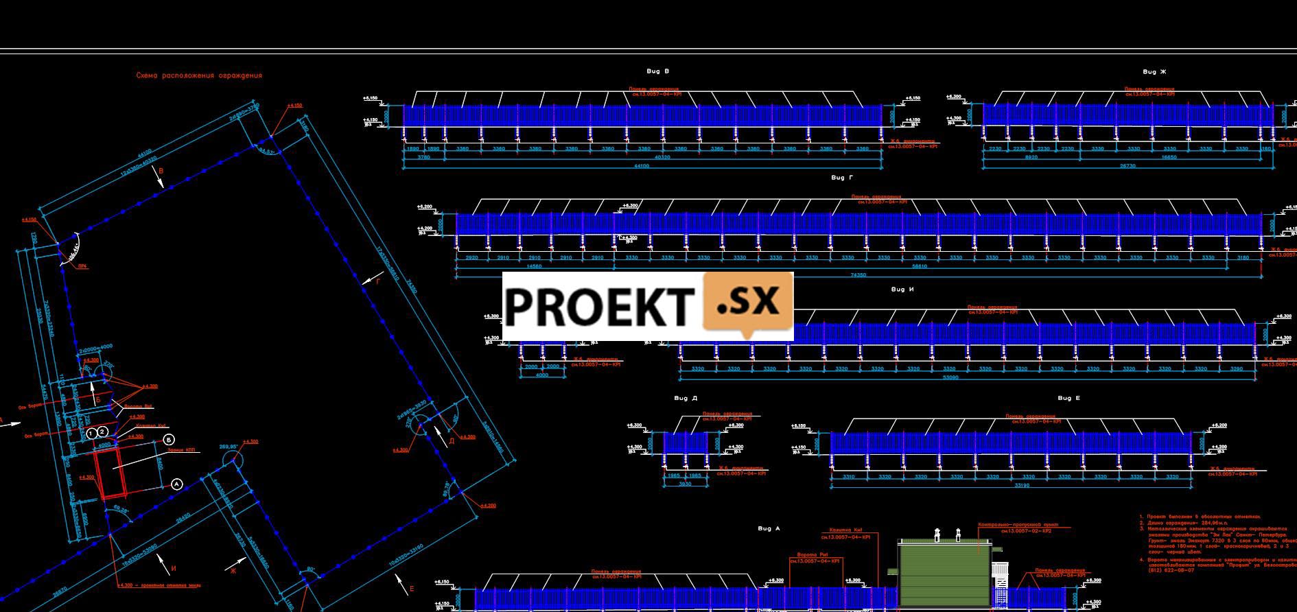
The area of the territory for engineering and environmental surveys is 0,68 ha. The maximum depth of soil development at the construction stage is 10 m (at the location of the sewage pumping station). Annex 1 presents a situational plan and a master plan for the design site.
Economic indicators of the object
At current prices in December 2013 with VAT, thousand rubles
The estimated cost is determined in the amount - 105
Including:
Construction and installation works - 46
Equipment - 50
Other - 8
Refunds: 1025,11
In basic prices, excluding VAT thous.rub.
The estimated cost is determined in the amount - 465 478,14
Including:
Construction and installation works - 46
Equipment - 50
Other - 8
Refunds: 153,85
De-icing is carried out mainly by chemical methods, which leads to the entry of large masses of chemical reagents into water basins and soil massifs, polluting surface and ground waters and posing a threat to flora and fauna and humans. Storing snow for its natural melting in spring or dumping it into the river network of the city leads to significant changes in the chemical composition of the main components of the environment (soil, water, air). In this regard, it is necessary to effectively remove large snow and ice masses and their disposal with minimal technical and economic costs. The use of sewers to melt snow collected from roads is justified. The capacity of urban treatment facilities is sufficient to receive runoff from snow that has melted in snow melting points. This solution was used in this project. The estimated capacity of the stationary snow melting station is 7 m000/day (for snow). The need of the design object for electricity is: 3 kVA (snow melting point), power supply category - III (see Appendix 517). The project does not provide for the use of raw materials and secondary resources. Land plots seized for temporary and permanent use are not produced. The area of the site for the placement of a stationary snow melting point is 9 m². Special technical conditions for the development of the project were not required.
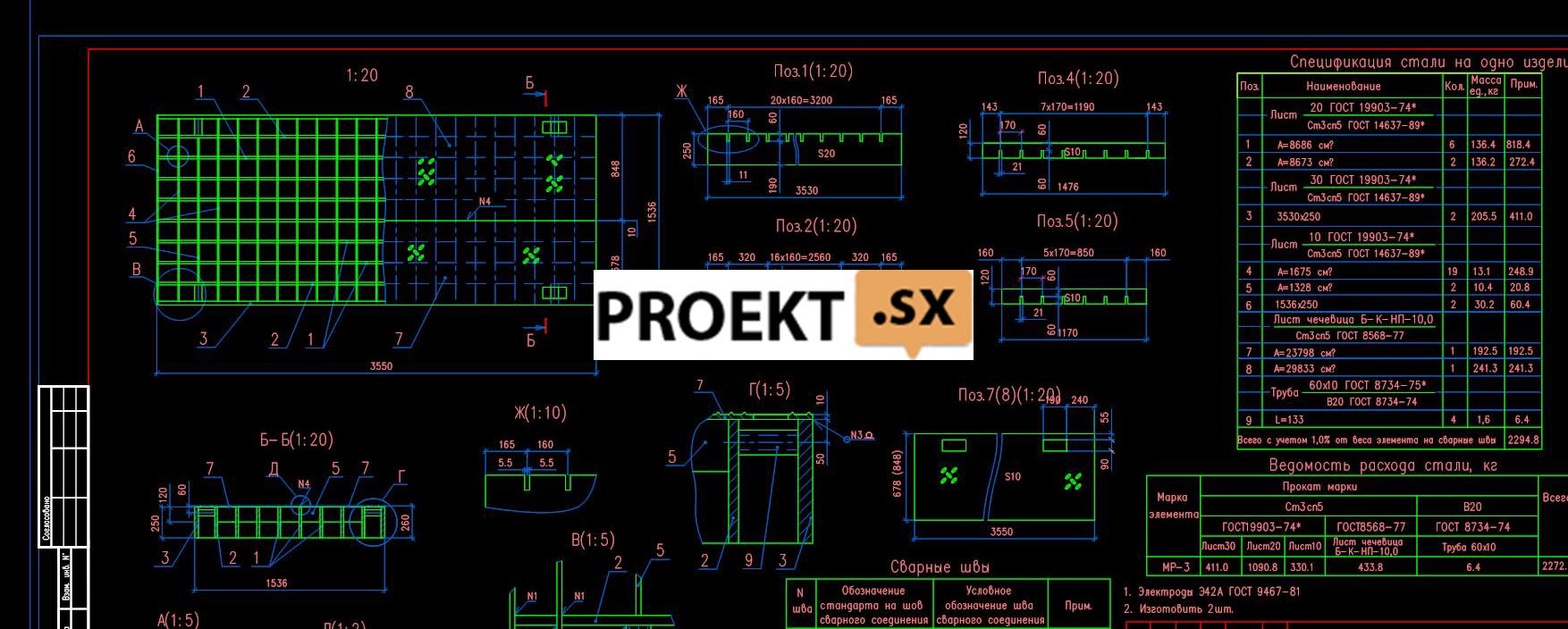
Structural solutions are developed in accordance with the presented initial data: Technological task on the drawings 13.0057-01-IOS7.ZD-AS.1 and 13.0057-01-IOS7.ZD-AS.1; The following soils take part in the geological structure of the site within the drilling depth (30,0 m) (wells No. 1, 2): EGE 1 - bulk soils - sands, with gravel, crushed stone, with construction waste, with an admixture of organic substances; layer thickness 5,5 m. EGE 2 - Sands are silty, medium density, gray, saturated with water; layer thickness 3,5 m. Porosity coefficient 0,750. Indicators of strength and deformability: φ=240, c=0,01 kgf/cm2, E=110 kgf/cm2. EGE 3 - Light silty loam, layered, with interlayers of sand, gray, fluid-plastic; layer thickness 2.5m. Porosity coefficient 0,819. Indicators of strength and deformability: φ=140, c=0,11 kgf/cm2, E=80 kgf/cm2. EGE 4 - Heavy silty loam, ribbon, brown, fluid; layer thickness 4.5m. Porosity coefficient 1,155 Indicators of strength and deformability: φ=90, c=0,07 kgf/cm2, E=50 kgf/cm2. EGE 5 – Light silty loam, layered, gray, fluid-plastic; layer thickness 2.0m. Porosity coefficient 0,96 Indicators of strength and deformability: φ=110, c=0 kgf/cm1, E=2 kgf/cm70. EGE 6 - Silty, gray, plastic sandy loam; layer thickness 1.5m. Porosity coefficient 0,607. Indicators of strength and deformability: φ=220, c=0,09 kgf/cm2, E=90 kgf/cm2. The snow-melting chamber is a structure measuring 39.78m x 20.7m in axes, 6.8m deep from the ground level (bottom bottom). For a relative mark of 0.000m, the level of planning was taken, corresponding to the absolute mark of +4.200 in the Baltic system of heights. The design of the snow melting chamber consists of load-bearing external walls, load-bearing internal walls and columns, spacer beams, a foundation in the form of a slab that acts as the bottom of the tank and a metal deck. Reinforced concrete structures of walls, partitions, foundations, columns, spacer beams are made monolithic. The geometric immutability of the structure is ensured by the joint work of the bottom, walls, columns and beams. The junctions of the spacer beams to the walls, as well as the junctions of the crossbars to the columns and the junctions of the columns to the foundation slab in frame structures are made rigid. Metal flooring in the form of separate removable gratings rests freely along the short sides on the outer and inner walls and the crossbar of the longitudinal frame structure. The foundation slab rests on an elastic base and is a support for wall and column structures. The snow melting chamber is designed for a temporary vehicle load, a load from stationary crushers of individual production (SDIP) and a load of sediment from melted snow. The maximum temporary vehicle load is 20,0 tons per rear bogie. The load from stationary crushers is 8 tons per 1 support. The calculation was performed using the calculation complex SCAD version 11.5. At the base of the structure are (EGE 2) silty sands of medium density, gray, saturated with water. The thickness of the layer ranges from 1600 to 2000mm. Underlying layers: EGE 3 - light silty loam, layered, with sand interlayers, gray, fluid-plastic; EGE 4 - heavy silty loam, ribbon, brown, fluid. When developing these soils, do not subject them to dynamic loads, under which they liquefy and lose their inherent in their natural state, structural coherence and bearing capacity. When excavating a pit, all measures should be taken to preserve the natural structure of soils in its bottom part. After excavation of the soil of the excavation to the design mark (elev. -6,870), the Tefond Plus Membrane is laid along the bottom of the excavation in 1 layer on a leveled sandy base and concrete preparation is carried out from concrete class. B15 on sulfate-resistant Portland cement on fine aggregate 50 mm thick. The project provides for the construction of a snow-melting chamber made of monolithic concrete of class B25 F150 W6 on sulfate-resistant Portland cement with reinforcement of class A240 and A400. The bottom of the chamber is designed with thicknesses 800 mm, along which monolithic concrete of class B15 F150 W4 is laid to create a slope (for the convenience of cleaning the chamber). The outer walls of the chamber are designed with a thickness of 600 mm, the longitudinal middle wall - with a thickness of 500 mm. The surface of the monolithic concrete of the bottom is sheathed with metal sheets 10 mm thick, the inner surfaces of the walls and columns - with metal sheets 8 mm thick to a height of 1,0 m. from the bottom. Metal sheets made of steel 15KhSND prevent damage to the concrete surface when cleaning the chamber. The metal sheathing sheets are installed using Hilti chemical anchors with a staggered pitch of 500 mm on a 88 mm thick EMACO S20 grout. The corners of columns and beams are protected from mechanical damage by embedded parts from rolled corners. Waterproofing of concrete surfaces of walls in contact with the ground: waterproofing membrane "RauFlex" th. 3mm on the bitumen-polymer primer No. 01 produced by TechnoNikol. Waterproofing of internal concrete surfaces is arranged with the material "Strimmix" with a total thickness of 4 mm. An anti-corrosion zinc-rich composition is applied to the embedded parts: primer "Cynotan" 1 layer 80 microns thick, topcoat - "Ferrotan" 3 layers with a total thickness of 100 microns. In places of input and output of engineering communications, glands are laid in the walls. The top of the snow-melting chamber is covered with removable custom-made metal gratings made of rolled sheets, which provide access to the drainage channel for cleaning. Waterproofing of metal structures of ceilings according to the system: primer - Zinotan - 1 layer 80 microns thick; cover layer - Ferrotan - 2 layers with a total thickness of 200 microns. The total thickness of the coating is 280 microns. The chamber is equipped with a semi-submersible partition for collecting oil products and a semi-submersible partition made of gratings with 80 mm gaps. 4 lattice containers are installed in the outlet chamber. In the partition separating the outlet chamber from the outlet corridor, 2 slide gates are installed. The top plate has 6 openings for the gate valves of the supply pipes.
Checkpoint (code 13.0057-02 КР1)
The checkpoint building is two-storey, rectangular in plan with dimensions of 8,4 × 4,0 m in the axes, and a height of 6,325 m. The level of the clean floor of the checkpoint corresponding to the absolute mark of +0.000 in the Baltic height system is taken as a relative mark of 4.450m . Within the depth of engineering-geological studies (well No. 5), the geological structure includes: - EGE 1 - bulk soils - sands, with gravel, crushed stone, with construction waste, with an admixture of organic substances; - EGE 2 - Sands are silty, medium density, gray, saturated with water. According to engineering-geological surveys, there are bulk soils at the base of the foundation of the building (design resistance Ro = 0.8 kgf / sq. cm). The total load on the foundation soil from the structure, taking into account temporary and permanent loads on the ceiling and coating, is 0.2 kgf/sq.cm. The foundation of the building is a shallow reinforced concrete monolithic slab h=300mm, which rises 70 mm relative to the ground level. Monolithic concrete slab class. B25, W6, F150 on sulphate-resistant Portland cement, reinforced in the upper and lower zones with bars of 12AIII (A400) rebar with a pitch of 200mm. Under the slab, concrete preparation h = 100 mm from concrete of class XNUMX is provided. B7.5 on sulfate-resistant Portland cement on fine aggregate, waterproofing (2 layers of waterproofing) and sand pad h=300mm with compaction up to γsk.=1,65 t/m³. To install the metal frame of the structure on a monolithic reinforced concrete slab, embedded parts are provided. Sleeves are installed in the slab to pass communications on the instructions of the EA and VK departments. Embedded parts are coated with anti-corrosion zinc-rich primer Zinotan, layer thickness 80 microns. To prevent seasonal freezing and eliminate frost heaving of soils under the slab and under the blind area around the slab, a heater is provided - Expanded polystyrene XPS-35 100 mm thick. The laying of sewer pipes under the slab is carried out before laying the insulation and concreting the slab. The lightning protection circuit (according to the EA drawings) is installed before the insulation is laid under the blind area. For a steel external staircase, separate monolithic foundations are provided from concrete class. B25, W6, F150 on sulfate-resistant Portland cement. The backfilling of the sinuses of the pit is carried out with sand of medium size in layers of 20 cm with compaction of each layer to γsk.=1,65 t/m³. The building is two-story, with dimensions in plan of 4,0 x 8,4 m. There is a metal staircase to get to the 2nd floor. The frame of the building is metal, consisting of racks, floor beams (covering) and ties. A steel corrugated board is installed along the metal beams of the floor for the installation of a monolithic reinforced concrete floor. Racks and half-timbered crossbars are provided for fastening wall sandwich panels. Roofing sandwich panels rest on roof beams. The spatial rigidity and stability of the building is ensured by the joint work of racks and beams, a rigid floor disk and the installation of vertical and horizontal ties. To perceive the wind load, horizontal wind crossbars are installed along the walls. Bearing structures (pillars, beams, ties) are protected with an anti-corrosion fire-retardant composition to achieve fire resistance R90: Primer GF-021 (GOST 25129-82) 50 microns thick on a surface cleaned of dirt, scale, dust and rust; fire-retardant paint "Thermobarrier" see the thickness of the coating layer on the sheets of the project. Fachwerk elements of the Federation Council, the Russian Federation should be protected from corrosion with materials of the ZINOTAN composition, anti-corrosion, zinc-filled: primer - ZINOTAN in 1 layer 80 microns thick on a surface cleaned of dirt, scale, dust and rust; coating - Polyton-UR in 1 layer with a thickness of 60 microns and then Polyton-UR in 2 layers with a thickness of 60 microns.
Crusher control pavilion (code 13.0057-03 КР1)
The building of the crusher control pavilion is two-storied, with plan dimensions of 2,70 x 5,50 m. The level of the finished floor of the crusher control pavilion corresponding to the absolute mark of +0.000 in the Baltic height system is taken as a relative mark of 4.650m. Within the depth of engineering-geological studies (well No. 4), the following take part in the geological structure: - EGE 1 - bulk soils - sands, with gravel, crushed stone, with construction debris, with an admixture of organic substances; - EGE 2 - Sands are silty, medium density, gray, saturated with water; - EGE 3 - Loams are light silty, layered, with interlayers of sand, gray, fluid plastic. According to engineering-geological surveys, there are bulk soils at the base of the foundation of the building (design resistance Ro = 0.8 kgf / sq. cm). The total load on the foundation soil from the structure, taking into account temporary and permanent loads on the ceiling and coating, is 0.3 kgf/sq.cm. The buried part of the building is an electrical cable basement. The base plate of the bottom h=300mm from monolithic reinforced concrete class. B20, W6, F150, on sulfate-resistant Portland cement, reinforced in the upper and lower zone with rebars of 12AIII (A400) reinforcement with a pitch of 200 mm. Under the slab, concrete preparation h = 100 mm from concrete of class 7,5 is provided. B 2 on sulfate-resistant Portland cement and waterproofing - 20 layers of waterproofing on bituminous mastic. The walls of the basement are reinforced concrete monolithic from concrete class. B4, W150, F12, on sulfate-resistant Portland cement, reinforced with vertical rods from reinforcement 400AIII (A2). Waterproofing - bitumen-polymer mastic "Slavyanka" in 4 layers with a total thickness of 35 mm on the bitumen primer "Slavyanka". The walls are insulated with Expanded polystyrene XPS 100 200 mm thick. For the passage of pipelines in the walls, metal and chrysotile-cement pipes are provided, for fastening cables - embedded parts. Basement ceiling - reinforced concrete monolithic ribbed structure h = 20mm made of concrete class. B4, W150, F12, on sulfate-resistant Portland cement, reinforced in the upper and lower zone with rebars of 400AIII (A200) reinforcement with a pitch of 1mm. The ribbed structure provides openings for cable passage, framed by embedded metal corners, and an opening with a metal staircase leading to the basement, covered with a removable metal shield. Embedded parts for fixing the metal frame of the pavilion are provided in the ceiling structure. Embedded parts and metal products are treated with an anti-corrosion zinc-rich composition: primer "Cynotan" 80 layer 2 microns thick, top coat - "Polyton-UR" 60 layers 2 microns thick. An external steel staircase is provided for climbing to the XNUMXnd floor. To support the stairs of the pavilion, monolithic foundations were made. The frame of the building is metal, consisting of racks, floor beams (covering) and ties. Racks and half-timbered crossbars are provided for fastening wall sandwich panels. Roofing sandwich panels rest on roof beams.