Did not you find what you were looking for? Ask us! We have archives of 140 TB. We have all modern reuse projects and renovation projects for Soviet standard buildings. Write to us: info@proekt.sx
Business center project

Project documentation without estimates and the results of engineering surveys for the completion of the reconstruction of an unfinished construction facility for the building of a class A business center with underground parking (parking)
Technical and economic indicators
Plot area, ha: 0,23
Building area, m2: 2
Total area of the building, including, m2: 21
Underground parking, m2: 4
Construction volume, including m3: 84600,0
Underground parking, m3: 3050,0
Number of floors above ground, fl.: 9
Number of underground floors (car parks), floors: 2
Architectural and space-planning solutions
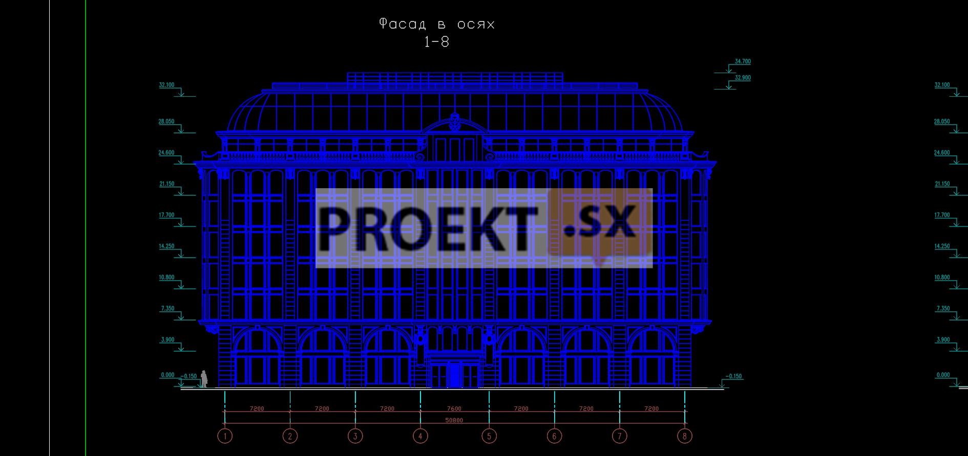
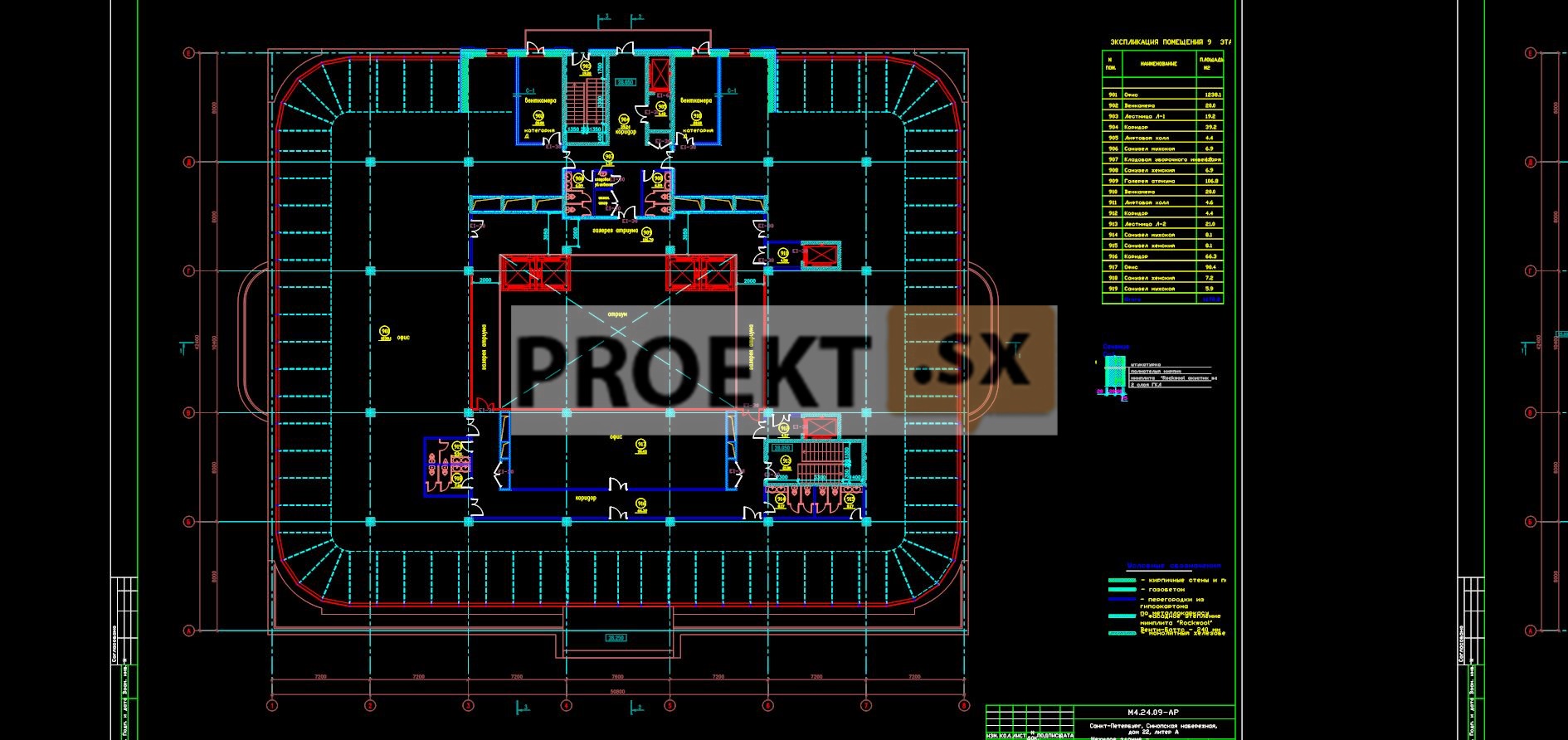
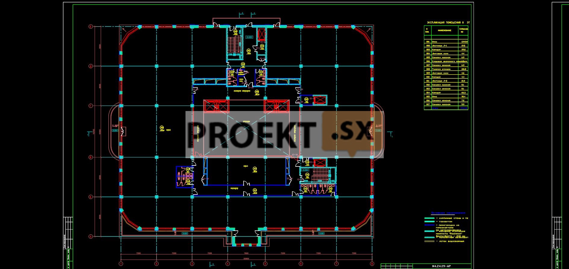
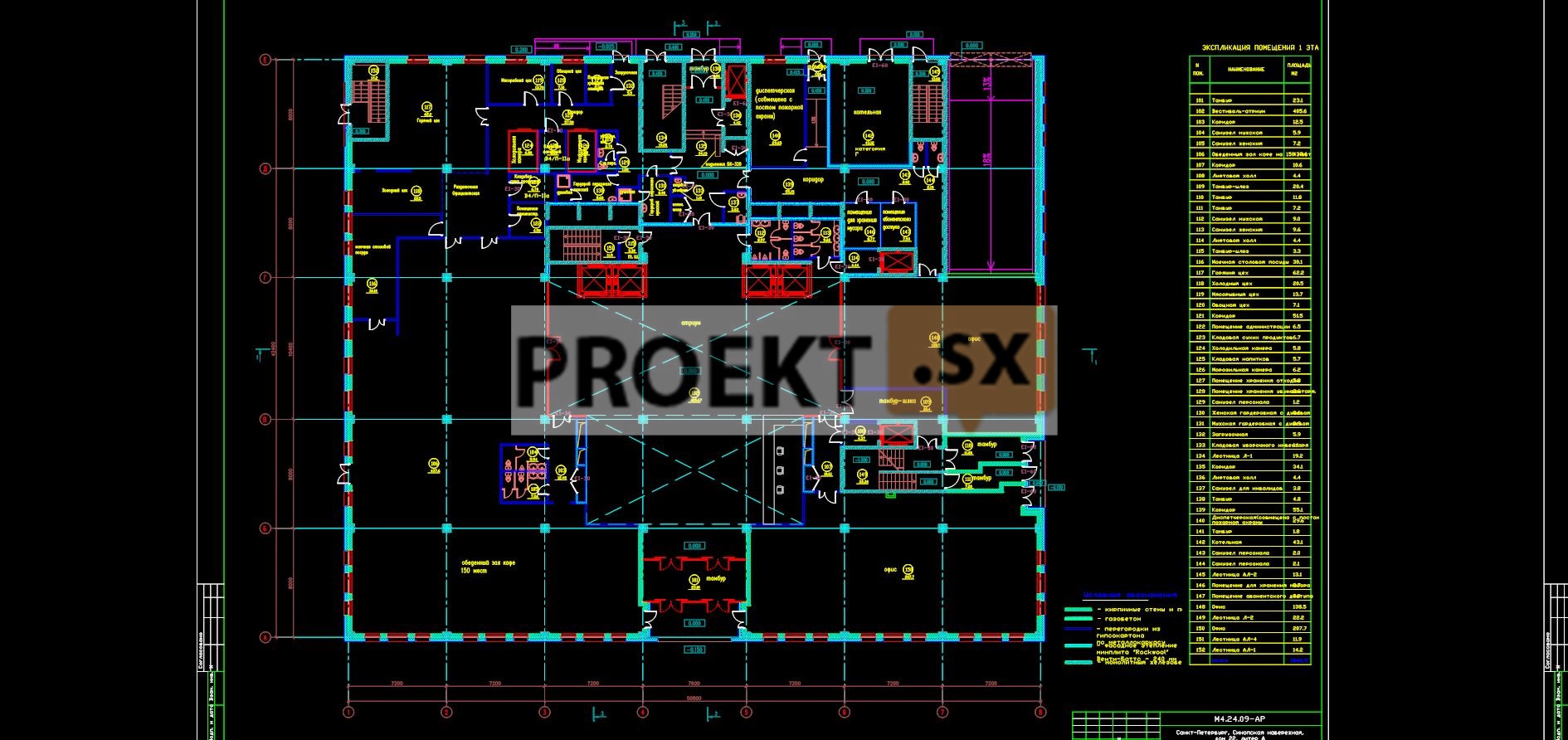
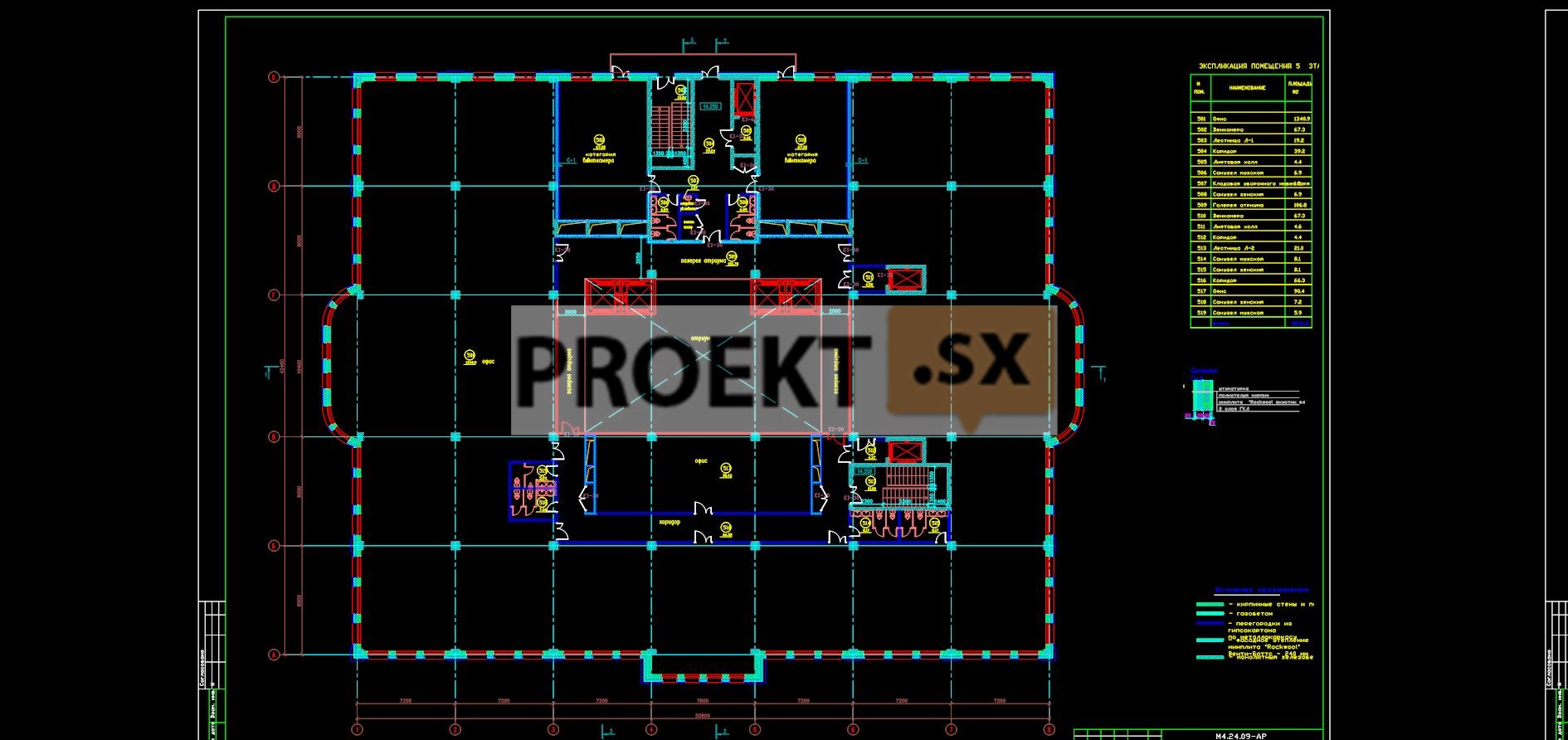
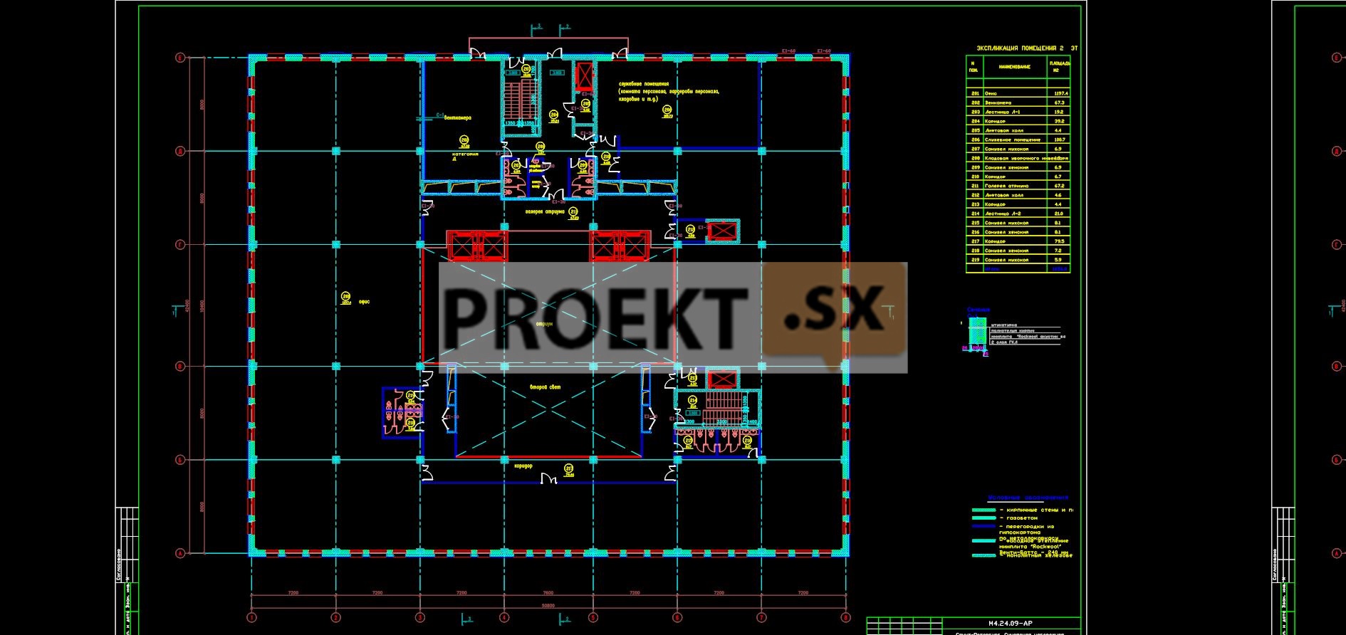
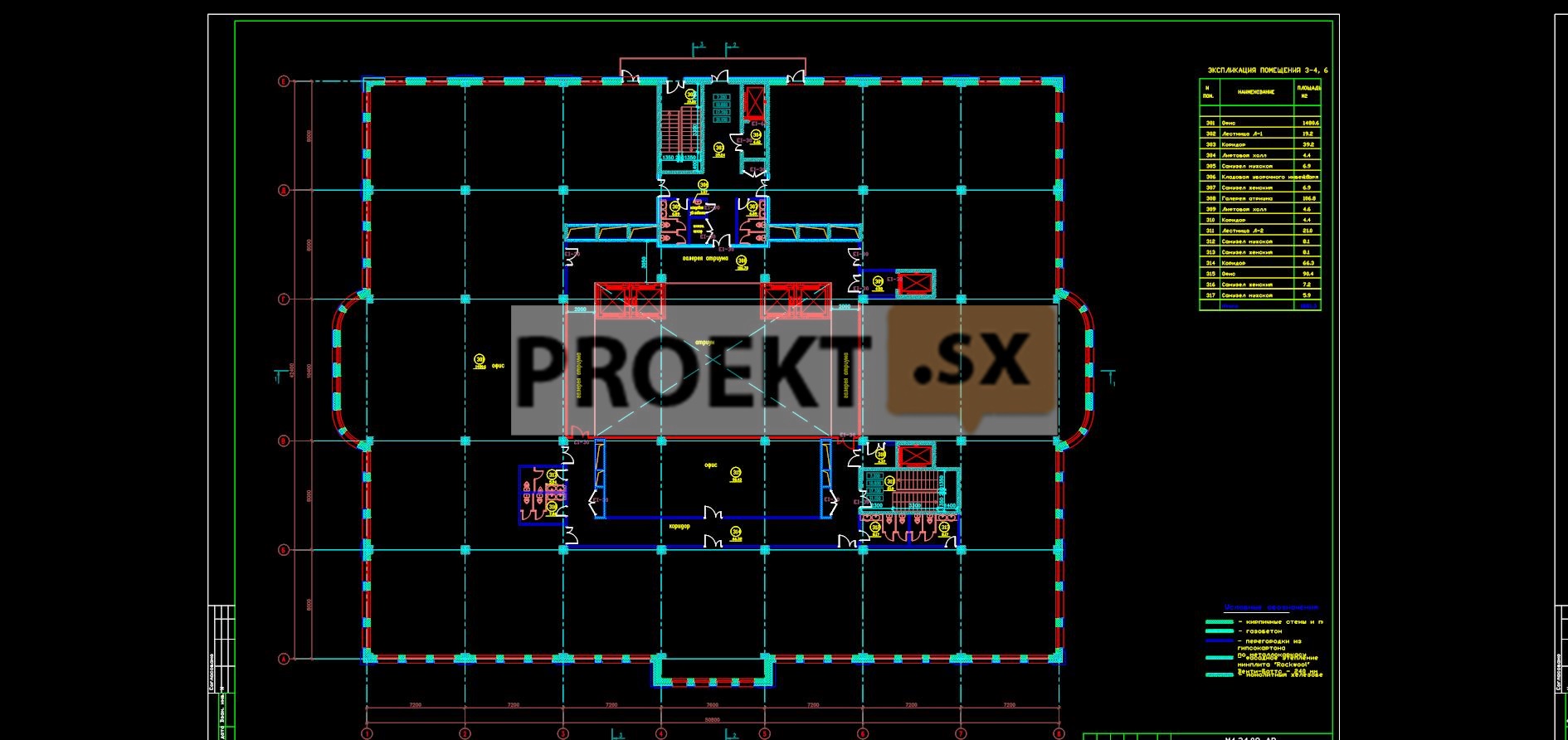
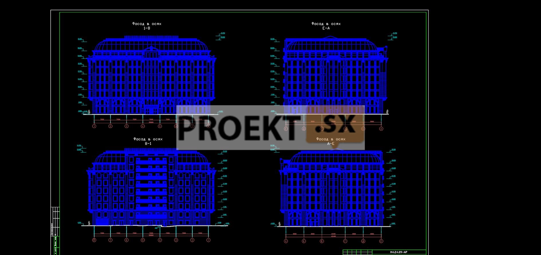
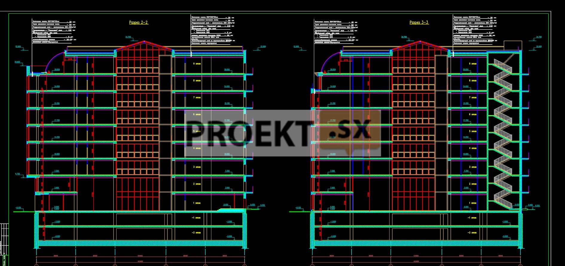
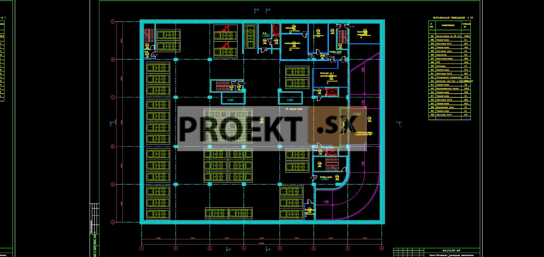
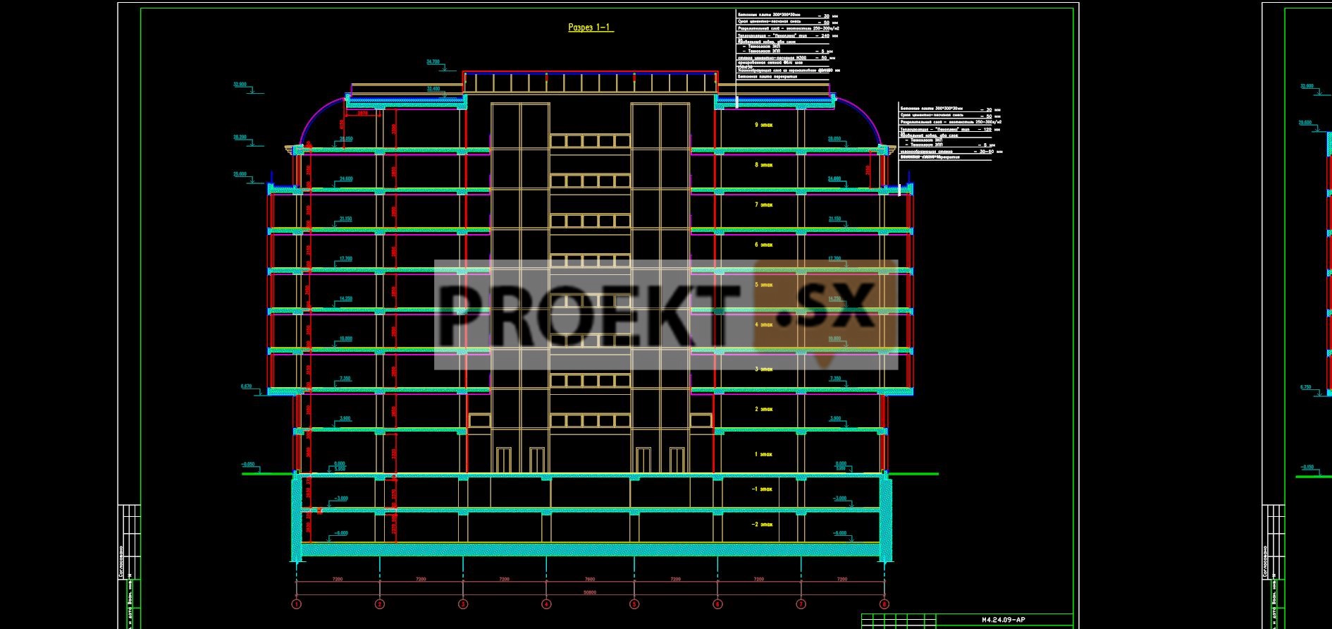
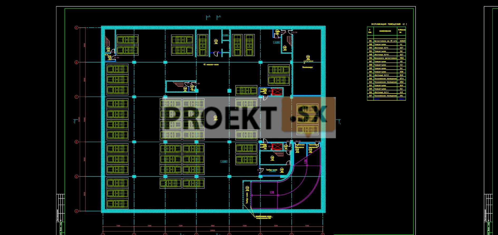
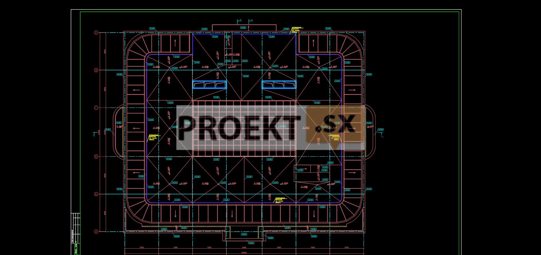
A business center building with an underground parking lot was designed, rectangular in plan, 9 floors with dimensions in the extreme axes of 50,80x42,40 m. For a relative mark of 0,000, the level of the finished floor of the 1st floor was taken. The maximum height of the building from the planning ground level to the top of the parapet is 33,1 m. The main entrance to the building of the business center is designed from the side of the embankment. A vestibule-atrium was designed in the center of the building, along the perimeter - office space, utility and technical rooms. On the ground floor, at the level of 0,000, a lobby, a cafe, an office space, bathrooms, a control room combined with a fire department post, utility rooms, and a built-in gas boiler room are designed. From the second to the ninth floor, office space, bathrooms and utility rooms are designed. The layout of office premises is free. Ventilation chambers are designed on the second, fifth and ninth floors. The height of the floors of the office part is 3,45 m, the height of the first and ninth floors is 3,9 m, the height of the basement floors is 3,0 m. For vertical communication between floors, seven elevators are designed - four passenger panoramic elevators with a carrying capacity of 1600 kg and cabin dimensions of 1750 x 1750 for moving from the 1st floor to the 9th floor, one passenger-and-freight elevator with the possibility of transporting fire departments with a carrying capacity of 1125 kg and cabin dimensions of 1200x2100 for moving from of the upper floor of the car park and above to all floors of the building, two passenger-and-freight elevators with a carrying capacity of 1125 kg and cabin sizes of 1200x2100 for moving from the lower floor of the car park and above to all floors of the building. In the office part, two staircases of the H1 and H2 type were designed for evacuation, the stairs are dispersed and have exits directly to the outside. External walls from the 1st to the 7th floors - insulated reinforced concrete frame with partial brick filling and hinged ventilated facade made of polished limestone. The outer walls of the 8th and 9th floors are steel frame filled with stained-glass windows. The plinth is monolithic reinforced concrete with polished limestone cladding. Partitions in the basement and on the ground floor are brick, plastered on both sides. Partitions of the office part - frame-sheathing. The cover is flat, with an internal drain, part of the cover is occupied by a translucent gable cover of the atrium. The building has a built-in underground 2-storey car park for 84 cars. The floor elevation of the first underground floor is -3.000, the second underground floor is -6,000. The height of the underground floors is 3,0 m. In the car park, the engineering service rooms of the car park and the building of the business center were designed. Separate emergency exits are provided from the parking lot through three H3-type stairs, which have direct access to the outside. Entrance to the car park is provided through an internal closed ramp from the side of the intra-block passage. External walls - from monolithic reinforced concrete, made according to the "wall in the ground" technology from hydrophobic concrete. The project documentation provides for the organization of the accessibility of the building for people with limited mobility at the level of the first floor and at the level of the upper floor of the car park, where parking spaces for the disabled are provided. On the ground floor there is a bathroom with a universal cabin.
Structural and space-planning solutions
Structural solutions for completing the reconstruction of an unfinished construction site are developed taking into account the location of the building in the existing building. In the zone of influence of the new construction is the house number 14; No. 24; 26 along Sinopskaya embankment. Inspection of buildings and photographic fixation of defects were completed. House No. 14, built in the late 20th century, is a five-story building in a reinforced concrete frame with hinged facades and foundations on a pile foundation. The buildings are assigned to category 1 of the technical condition of structures according to TSN 50-302-2004. Houses No. 24 and 26, built before 1917, consist of several one-three-story buildings, brick, floors - wooden, steel roofs - on a wooden truss system, foundations - on a natural foundation. Buildings are assigned to category 3 of the technical condition of structures according to TSN 50-302-2004. Buildings of house No. 24 - letters A2; A3; IN; D, which are located in close proximity to the new construction, are in an unacceptable state according to SP13-103-2003. The project provides for strengthening the buildings of house No. 24 in order to reduce the susceptibility of the building to uneven precipitation and transfer it to the 2nd category of the technical condition of structures, for which additional precipitation up to 3,0 cm is allowed. The new building belongs to the normal level of responsibility. The load-bearing structures of the building are a monolithic reinforced concrete spatial frame with an irregular grid of columns. The main grid of columns is 7,2 x 8,0 m with one span of 10,4 m. Columns with a section of 600 x 800 mm (underground floors); 600x600 mm. Floor slabs and coatings 220 mm thick, 240 mm, 300 mm - "beamless" with support on the frame columns. The strength of the plates for punching is provided by the transverse reinforcement of the plates. In a span of 10,4 m and along the outer perimeter of the building, floor slabs rest on monolithic beams with a section of 800x500 (h); 600x450(h). Remote elevator shafts - a steel frame with glass filling with floor-by-floor fastening to the supporting structures of the building. The overall stability and rigidity of the building is ensured by the spatial work of vertical, horizontal stiffening diaphragms and structural elements of the frame. The role of vertical stiffening diaphragms is performed by internal walls and walls of stair-elevator units with a thickness of 200 mm, floor slabs are horizontal stiffening diaphragms. The main load-bearing structures of the building are designed to meet fire resistance requirements in accordance with STO 36554501-006-2006. The calculation of building structures was performed using the SCAD 11.3 software package. The material of above-ground monolithic structures is concrete of class B40; B30; B25; fittings of class A400. External walls - non-bearing, floor-by-floor, supported by ceilings and consist of bricks 250 mm thick with a hinged facade system "U - KON", partially - stained glass glazing. The walls are fastened to the load-bearing structures of the building by flexible connections. Structural solutions for fastening the hinged facade system and stained-glass windows to the supporting structures of the building are developed in the working documentation in accordance with the current technical certificate of the Ministry of Regional Development of the Russian Federation. Structural solutions for the underground part of the building. At the construction site, since 2006, there has been a pit with sheet piling steel fencing, with driven piles and with a section of a slab - grillage made of monolithic reinforced concrete. Examination of the structures of the excavation has been completed. During the survey, the unstable state of sheet piling and the impossibility of using existing structures for a new building were established. In this regard, the project provides for the dismantling of the slab section - grillage, sheet piling and backfilling of the pit to an absolute mark of 4,700 m The new building is designed with a developed underground part to accommodate a two-level car park. The depth of the pit for the construction of the underground part of the building is about 7,2 m. The foundation of the building is a monolithic reinforced concrete slab - a grillage 1000 mm thick rests on bored piles with a diameter of 620 mm. Piles are made under the protection of a casing pipe with excavation from the backfill level of the existing pit from the absolute mark of 4,700 m to the absolute mark of the bottom minus 20,150 m. The estimated length of the piles is 19 m from the bottom of the slab - grillage. To carry out work on the installation of monolithic structures of the underground part of the building, the pit is fenced in the form of a monolithic reinforced concrete wall with a thickness of 800 mm and 1000 mm (wall parallel to house No. 24 on Sinopskaya embankment), made using the "wall in the ground" technology. The enclosing structure performs the functions of protecting the walls of the pit from collapse, from groundwater and is the basis for the supporting structures of the building. The height of the pit enclosure wall from the ground is 25,0 m with an absolute bottom mark of minus 20,080 m. At the base of the retaining wall and piles there are silty sandy loam with gravel and pebbles, plastic with a total deformation modulus E = 280 kgf/cm2. The design load on the pile is determined by calculation according to SP 50-102-2003 and is 150 tf. The project provides for static load testing of piles to confirm the accepted load. The excavation enclosure wall is made under the protection of a clay bentonite mortar with waterproofing pads in the vertical concreting joints. Excavation of soil from the pit is carried out through technological holes in the ceiling above the second underground floor. The stability of the wall is ensured by a monolithic reinforced concrete slab in one level (the slab above the second underground floor). The erection of monolithic underground structures is carried out according to the “top-down” technology with sequential execution of floors, foundation slab - grillage and frame structures. Material of underground structures: B40 class concrete (columns); В30 (piles; fence wall); В25 (overlappings) W6 (piles); W8 (fence wall); F 100; F150; fittings of class A400. Assessment of the geotechnical situation at the construction site, the impact of construction on the surrounding buildings, the calculation of the load-bearing structures of the underground part of the building were performed using FEM models computer systems; SCAD 11.3. The enclosing wall in the ground is designed for vertical loads from above-ground structures; on horizontal loads from the ground and from the weight of existing adjoining buildings. The maximum design settlement of the designed building is 2,1 cm. The maximum settlement of the surrounding buildings from all influences (ditching and loading the foundation with the weight of the designed building) is 2,9 cm, which does not exceed the allowable values for buildings of the 2nd category of the technical condition of structures To perform construction and installation work on the construction of the underground part of the building, a project for the production of works is being developed to ensure the strength and stability of existing communications and buildings of the surrounding area. Waterproofing the basement from groundwater: the use of concrete of a higher water resistance grade W8 for the grillage and the wall of the excavation, the use of waterproofing pads in the working seams of concreting. For the entire period of work, the project provides for monitoring the condition of neighboring buildings with control of settlements, horizontal displacements, possible opening of cracks and the magnitude of dynamic effects. Zero cycle works are accompanied by observations of horizontal displacements of the excavation fence and changes in the position of the groundwater level in the adjacent territory. The relative elevation of 0,000 corresponds to the absolute elevation of 5,950 m.